Simulation & Verification
Find it on the screen, not on the spindle.
A crash is rarely just a crash. It is a spindle rebuild, a scrapped billet, a machine out of service, a delivery date missed and an operator who no longer trusts the programme. Verification is the cheapest insurance in the building, and we treat it as standard rather than as an option.
What we actually do
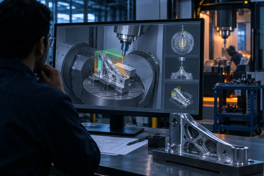
We simulate the posted G-code — not the CAM toolpath. This matters more than it sounds: the CAM system simulates what it intended, while the machine runs what the post actually produced. Verifying the real NC code is the only way to catch post processor errors, and those are exactly the errors that put a tool through a fixture.
The simulation runs against a model of your actual machine: its kinematics, travel limits, table and head geometry, tool changer and controller behaviour. Rotary limits, singularities and near-misses that only exist on a specific machine show up where they belong.
Beyond crash detection, we check what the programme leaves behind. Gouges and excess stock are compared against the design model, and air-cutting time is identified and removed — which on long-cycle aerospace parts routinely finds double-digit percentages of wasted spindle hours.
What is included
Full machine simulation
Your real kinematics, travels, tool changer and controller behaviour — not a generic machine.
Collision & near-miss detection
Tool, holder, spindle, fixture, part and machine structure all checked against each other.
Gouge & excess stock analysis
Machined result compared against the design model, feature by feature.
Air-cut & cycle time reduction
Non-cutting motion identified and removed, with the time saved quantified.
Post processor validation
Errors introduced between CAM and G-code found and fixed before they reach a machine.
Verification report
Documented evidence of what was checked and what was found — auditable, and useful for your customer.
How we approach it
The same sequence on every job, so you always know where your part is.
Build the machine model
Kinematics, travels, table and head geometry, tool changer and controller emulation configured once and reused.
Load the real programme
Posted G-code, tool assemblies with holders and stick-out, fixture assembly and stock definition.
Run and detect
Collisions, near-misses, overtravel, rotary limits and singularities identified with the offending block.
Compare against design
Machined result checked for gouges and excess stock, feature by feature.
Correct and re-verify
Issues fixed, programme re-run clean, and the whole thing documented.
What you receive
Every deliverable is yours outright — native files included. No lock-in, no dependency on us to make the next revision.
| Deliverable | Detail |
|---|---|
| Verification report | What was simulated, what was found, what was changed — with screenshots |
| Corrected G-code | The programme with every issue resolved and re-verified after correction |
| Machine model | Your configured machine simulation model, reusable on every future job |
| Cycle time analysis | Cutting versus non-cutting breakdown with the reduction opportunities listed |
| Stock comparison | In-process and final stock condition compared against the design model |
Common questions
Yes, and the difference is the one that matters. CAM simulation shows what the CAM system intended; it does not run the posted code and it usually does not model your specific machine. Post processor errors, rotary limit violations and machine-specific singularities are invisible to it — and those are the failures that cause real crashes.
Absolutely, and it is a common way for clients to start with us. Send the posted code, the tool list, the fixture model and your machine details. You get a verification report and corrected code, and we do not need to have written the programme to check it.
No. Kinematic diagrams, travel specifications, the machine manual and photographs are enough for most builds. The model is configured once and then reused for every subsequent programme on that machine.
Send us a drawing. We’ll send back a plan.
Share a 2D print, a STEP file or a scope note. You get a written response with feasibility, approach and an indicative timeline — no obligation, and your data stays yours.