Fixture & Tooling Design
The fixture is half the programme.
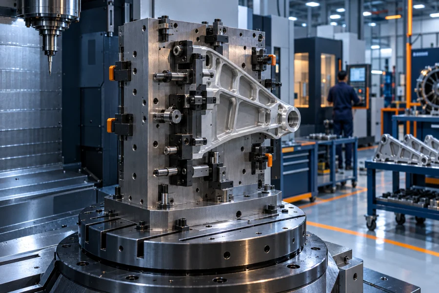
You can have a perfect toolpath and still scrap the part, because the fixture flexed, the clamp was in the way of op 3, or the operator could load it two ways round. Workholding is a design problem, and it deserves to be treated as one.
What we actually do
We design the fixture around three things at once: the part's datum scheme, the machine's working envelope, and the toolpaths that have to reach past it. Designing for any one of those in isolation is how clamps end up where the cutter wants to be.
Rigidity is engineered rather than assumed. Clamping forces are placed to push the part into its locators instead of bending it, support is provided under the cutting forces, and thin or unsupported features get specific attention — because a part that deflects under the cut will measure fine on the bench and wrong in the fixture.
Every fixture is delivered as a full 3D assembly so it can go straight into machine simulation. The simulation then sees exactly what the machine will see: clamps, locators, base plate, bolt heads and all.
What is included
Dedicated fixture design
Purpose-built workholding for a specific part and operation, engineered for rigidity and repeatability.
Modular & standard tooling
Built on vices, tombstones, chucks and modular systems you already own, to keep the cost sensible.
Multi-part & tombstone layouts
Higher part density per cycle where batch size justifies it, balanced against tool reach and swarf clearance.
Poka-yoke by design
Physically impossible to load wrong — asymmetric locators rather than a note on the setup sheet.
Full 3D assemblies
Modelled complete so machine simulation sees every clamp, bolt head and locator.
Manufacturing drawings
Detail and assembly drawings with tolerances, materials, hardware list and BOM.
How we approach it
The same sequence on every job, so you always know where your part is.
Fix the datum scheme
The locating strategy from the process plan drives the design — 3-2-1 principle applied properly, not approximately.
Concept and review
Two or three concepts with the trade-offs stated: cost against cycle time against changeover speed.
Detail design
Full 3D assembly with real hardware, engineered clamping forces and designed-in support.
Prove it virtually
Interference checked against every toolpath and the machine envelope before anything is manufactured.
Release for manufacture
Drawings, BOM and loading instructions issued as a complete package.
What you receive
Every deliverable is yours outright — native files included. No lock-in, no dependency on us to make the next revision.
| Deliverable | Detail |
|---|---|
| 3D fixture assembly | Complete native CAD assembly with all hardware, ready to drop into simulation |
| Detail & assembly drawings | Fully dimensioned and toleranced, with material specifications and finish callouts |
| Bill of materials | Every component listed, with standard hardware and modular items called out by part number |
| Loading instructions | Illustrated sequence for the operator, including clamping order and torque where it matters |
| Interference report | Clearance analysis against the toolpaths and the machine envelope |
Common questions
That is usually our first suggestion. Send us what you have — vice models, tombstone drawings, chuck and jaw details — and we will design to use it. New hardware only gets specified where the existing kit genuinely cannot do the job.
We are an engineering practice, so we design and document; manufacture goes to a toolroom. We are happy to work with your preferred supplier or to issue the package in a form any competent toolroom can quote from directly.
With support strategy first and clamping second — soft jaws, conformal supports, sacrificial tabs and staged clamp release as the part is machined. We also feed the deflection risk back into the programming so cutting forces are kept where the part can take them.
Send us a drawing. We’ll send back a plan.
Share a 2D print, a STEP file or a scope note. You get a written response with feasibility, approach and an indicative timeline — no obligation, and your data stays yours.